Wiring#
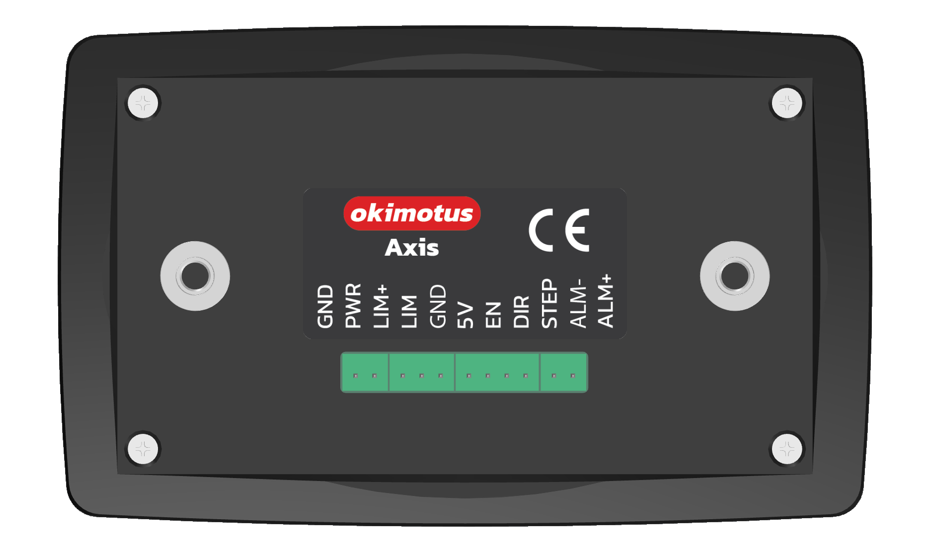
The preferred scheme to wire axis to a stepper/servo motor driver is the common anode method while common cathode still possible.
Configuring
Sensor type |
Limit pin trigger |
|---|---|
NPN NO |
Falling edge |
NPN NC |
Rising edge |
PNP NO |
Rising edge |
PNP NC |
Falling edge |

This is the image caption#

This is the image caption#

